dealcatcher
New member
Hi all,
In order to get the proper voltage to use an LED or incandescent E27 bulb, I was thinking of bypassing the ballast connected to the CFL myself. I'm pretty sure I've got it down, but I want to confirm a couple things with those of you who have experience here.
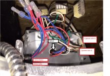
The first pic is just a picture of the jbox behind the recessed light fixture.
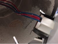
The second pic is just the 4 wires going from the ballast to the 4-pin GX24 CFL light socket.
1) In the first pic, do you know why I have two power wires going to the ballast? (In the pic, I've labeled the two power wires as wire #1 and #2. In each power wire, I have a live wire (black), neutral (white), and the copper (ground). I was just curious why I have two of each.
2) In the first pic, wires #3 (2 blue wires) and #4 (2 red wires), connect from the ballast to the 4-pin socket. Do you know why there are two blues and two reds? Seems strange that there are two of each. Is this because it's a 4-pin socket?
3) And last question, to bypass the ballast, I was going to cut the two live wires (black wires) from #1 and #2 and connect them to the two red wires #4 that go to the 4-pin socket. Then, I was going to cut the two neutral wires (white wires) from #1 and #2 and connect them to the two blue wires #3 that go to the 4-pin socket. Is this the way to bypass the ballast?
Thanks in advance for your help! I hate the look and warm-up period that comes along with CFLs and want to switch them out to the dimmable 3000k LED spotlights.
In order to get the proper voltage to use an LED or incandescent E27 bulb, I was thinking of bypassing the ballast connected to the CFL myself. I'm pretty sure I've got it down, but I want to confirm a couple things with those of you who have experience here.
The first pic is just a picture of the jbox behind the recessed light fixture.
The second pic is just the 4 wires going from the ballast to the 4-pin GX24 CFL light socket.
1) In the first pic, do you know why I have two power wires going to the ballast? (In the pic, I've labeled the two power wires as wire #1 and #2. In each power wire, I have a live wire (black), neutral (white), and the copper (ground). I was just curious why I have two of each.
2) In the first pic, wires #3 (2 blue wires) and #4 (2 red wires), connect from the ballast to the 4-pin socket. Do you know why there are two blues and two reds? Seems strange that there are two of each. Is this because it's a 4-pin socket?
3) And last question, to bypass the ballast, I was going to cut the two live wires (black wires) from #1 and #2 and connect them to the two red wires #4 that go to the 4-pin socket. Then, I was going to cut the two neutral wires (white wires) from #1 and #2 and connect them to the two blue wires #3 that go to the 4-pin socket. Is this the way to bypass the ballast?
Thanks in advance for your help! I hate the look and warm-up period that comes along with CFLs and want to switch them out to the dimmable 3000k LED spotlights.